|
What do you do when you track satellites? Satellites are put into
orbit to do a job i.e., take pictures of the earth, measure radio signals in space, relay messages from one place on the earth
to another, and even take men to, “where no man has gone before.” When
we put a satellite into space we have three basic needs; 1. Tracking, 2. Satellite status, and 3. Payload. Tracking – we must know where
and when the spacecraft is; Satellite status – we must know what equipment is on and
working, and how much power is available; Payload – we must receive experimental information.
When I first started in this business there were only a handful of satellites in orbit and no computers. The equipment we operated with in Quito, Ecuador
in 1962 had the same kind of vacuum tubes that the old fashioned radios used. We
technicians both operated and repaired the equipment. The first satellite I ever
tracked was called, “58 Beta.” Fifty-eight was the launch year and
Beta represented the second spacecraft launched that year. I also remember tracking
“62 Omnicom.” One of my early jobs was to check and replace inoperable
tubes in the electronic equipment. Since then, tubes gave way to transistors,
which gave way to integrated circuits, known as microchips or ICs.
The
first tracking systems were called Minitrack Tracking Stations. Minitrack interferometer
tracking data was received with the use of “ground plane antennas” called, linear dipole, metal frame skeletal
arrays. These antennas were made up of fixed pieces of metal mounted parallel
to the earth. The antennas were located in such a position as to detect the phase
of the spacecraft signals passing overhead. They were arranged so we would receive three sets of signals
from a satellite passing overhead, course, medium and fine. The combination
of the signals allowed us to pinpoint when the satellite passed overhead. These
three signals were applied on a moving strip chart along with a time code on the side.
A binary time code was produced from a standard time source received from the WWV national radio station out of Denver, Colorado. When the three phases of the satellite’s signal were lined up in the same time frame we would mark the spot and note the time indicated by the code. After the pass was over we would generate a Teletype message to Goddard Space Flight
Center with the exact time the satellite passed overhead. Goddard would use that
information to predict the time of the next crossing.
Another way we tracked satellites was with the Minitrack Optical Tracking System, or MOTS for short. The MOTS telescope/camera was located in a small building outside of the main tracking building. The top part of the building, with the roof, was built on rollers on a track. We would have to physically push the top away from the building to expose the telescope to the night sky. We would insert a case, which included a glass negative covered by a metal slide into
a mount at the base of the scope. We would point the telescope in the expected
direction the satellite would appear and wait. We would point the scope at the
location we expected the satellite to appear (We had predicts that told us in which direction and what time to look.) turn
on the star drive, and look through the viewfinder. The viewfinder had lines
to let us know what part of the sky would be photographed. The star drive would
keep the camera pointed at the stars in its field as the earth moved under them. Just
before the satellite crossed the field marked by the lines, we would pull the metal slide from its holder and film, exposing
the negative.
The device had a small spring-loaded plunger that would push against the negative’s mount at a rate that represented a time code. The results
of the plunger’s movement would make the stars look like small lines. The
satellite, because of its movement through the star field, would look like a streak across the field of stars with spikes
representing the time of the crossing. After the satellite finished its pass
we would re-insert the metal slide, remove the plate from the end of the telescope, slide the rooftop back (to cover the camera
and equipment) and take the freshly exposed negative to the main building and into the developing room. After we developed the film we would take it to a table on the main floor and lay it on a frame that had
a florescent light under it. Selecting a star chart of the correct area we would
lay it over the plate and position it so the stars lined up correctly. We would
select several data points and write the coordinates and time that the satellite crossed.
This information was sent via a Teletype message to Goddard and the plate mailed via a diplomat pouch provided by the
U.S. embassy. There were no specialist; one technician did the whole process.
Telemetry information, which included spacecraft status
and payload data, was received in another way. Antennas physically tuned to the
range of frequencies, that we expected to receive from spacecraft, were mounted on a platform that we were able to move in
azimuth (directions of the compass) and elevation. Inside the building were racks
of various electronic equipment designed to receive the different types of signal data.
There were also transmitter, and tape recording racks as well. The input
and output plugs from the various equipment were connected to coax cables, which were extended to a patch panel. Each spacecraft had different requirements that were spelled out in a handbook. We would check the handbook before a “pass” and use the patch panel to connect the equipment
together accordingly. The signals received and/or transmitted were also patched
to a number of “tracks” on a tape recorder. When the time came for
the satellite to come over the horizon, a technician would be positioned at the antenna control rack to keep the antenna pointed
at the satellite. We would have a prediction sheet mounted on a music stand
in front of us with a list of times, azimuth and elevation points, for the antenna.
There was no automatic tracking system in 1962 and we would have to watch the signal strength presented on a strip
chart for that purpose, and move the antenna azimuth and elevation controls to keep the strongest signal coming to the receiver.
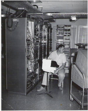
The picture below shows me tracking a satellite. The patch panel and antenna controls are on my right; the azimuth and elevation predicts are on the stand
in front of me; the signal strength strip chart (I am looking at) is on my left. The
cart in the picture supports a CRT (cathode ray tube) giving me a view of the telemetry signal from the spacecraft.
Enter supporting content here
|
| LARRY PARKER 1964 |
If we lost the signal we would use the prediction sheet
to re-point the antenna and try to reacquire the spacecraft. Another technician,
or field engineer as we were called, would lock the receiver on the satellite signal, turn the tape recorder on at the proper
time as well as check each track to see if we were recording the required signals. After
the pass, the tapes recorded were labeled, packaged, and sent by way of the diplomat pouch to Goddard. If needed, we would give the controllers at Goddard a “quick look” at the data. The strip chart of the telemetry data would be spread out on a long table.
Using a template to locate the starting point, we could read, by interpreting the pulses on the chart, the status or
payload information the controllers wanted, i.e. what camera was on, battery power, what experiments were on, and so forth. The “quick look” information would be sent directly to them by way of
a Teletype message. This could even be done during the pass with a direct communication
link to them. They could then instruct us, by Teletype, to transmit a tone or
combination of tones to the spacecraft to change its status before we lost the signal.
(Long distance phone calls for that purpose were prohibitive.)
Sending a signal of instruction to satellites was very primitive. We
would start by transmitting an RF (radio frequency) signal; we called a carrier wave, to the spacecraft. The transmitter had buttons on its face. Controllers would
instruct us to, “Push tones 4,7,2 followed 20 seconds later by tones 2, and 6.”
When pushed, the buttons would cause the carrier wave’s frequency to be modulated in seven different frequencies, which we called tones.
A tone, or combination of tones would cause the spacecraft to respond in the way the controller wanted, i.e. turn on
or off an experiment or camera. The “quick look” would tell the controller
if the spacecraft responded correctly before we lost the signal over the horizon.
By the mid sixties Minitrack stations had given way to STADAN
stations, i.e. Satellite Tracking And Data Acquisition Network stations. (Later, the MSFN [Manned Space Flight Network] and STADAN were merged to become the Spaceflight Tracking and Data Network [STDN]). I had been transferred to the Goldstone
tracking station in the Mojave
Desert. We were constantly updating our equipment and could now lock
onto the satellite and let our new AGC (Automatic Gain Control) receiver send signals to drive motors that would move the
antenna to follow the spacecraft automatically. Unified S-band (USB) tracking
was revolutionary for its time, enabling transmission of spacecraft command, telemetry, range and range rate (tracking), voice
and television using a single, combined data link. Range and range rate
was a process where we would lock onto a satellite’s signal, transmit to it and measure the time it took our signal
to return, as well as the change in frequency (Doppler) due to the satellite’s movement through space. During this time I received an outstanding achievement award with the comment, “For recognized achievement through the Bendix
Field Engineering Corporation suggestion system in conjunction with his suggestion concerning fabrication of a device to remove
magnetic tape from the reel.”
Technology That Produced Today’s Practical
Satellites
Between December 1966 and May 1974 a series of satellites named the Applications Technology
Satellite (ATS) (http://msl.jpl.nasa.gov/Programs/ats.html) were
launched to conduct approximately 30 technological experiments and approximately 10 scientific experiments. The ATS series of spacecraft were created to explore & flight-test new technologies and techniques for communications, meteorological
and navigation satellites. Some of the areas investigated during the program,
included yoyo de-spin stabilization, gravity gradient stabilization, complex synchronous orbit maneuvers, and a number of
communications experiments. The yoyo de-spin was a procedure where two weights
attached to wires were released on opposing sides of a spinning spacecraft and slowly extended. Like a skater extending his arms to slow his spinning body, the weights did the same for the S/C. The weights and wires were then released and allowed to fly off into space. The gravity gradient experiment was similar. Long “arms”
were extend from the non-spinning S/C and acted like a long pole that a wire walker would used to balance himself on a high-wire;
balancing the S/C over the gravity of the earth. I remember seeing video from
the S/C showing the long arms flopping as they were extended. The ATS flights
also investigated the geo-stationary orbit environment and prototyped many of the technologies
used on the Tracking and Data Relay Satellite System and other commercial communications satellites. The TDRSS became a series of geo-stationary satellites that replaced ground stations in foreign countries
by relaying a low orbiting spacecraft’s signal’s to the ground. This
new coverage allowed manned spaceflights to increase its 15 minutes
per 90 minutes orbital communications to up to 80 minutes. Although the ATS satellites were mainly intended as test beds, they also collected and transmitted
meteorological data and functioned at times as communication satellites. I had some unique experiences while working with these spacecraft.
ATS-1 (http://msl.jpl.nasa.gov/QuickLooks/ats1QL.html)
ATS-1
was launched on 12/7/1966, examined spin stabilization techniques, investigated the geo-stationary environment, and performed
several communications experiments. Its VHF experiment tested the ability to act as a link between ground stations and aircraft,
demonstrated collection of meteorological data from remote terminals, and evaluated the feasibility of using VHF signals for
navigation. It also transmitted educational programs and provided health, research, and community services to the US and several Pacific island countries, including the Cook, Mariana, Marshall
and Caroline Islands, West and American Samoa, Melanesia,
New Zealand, and Australia.
The mission also provided the first full-Earth cloud cover images. (I have a
picture of the earth, which was made up of several pictures. When you tilt it
you can see clouds moving across the earth.) I transmitted signals from our station
that configured the spacecraft to be used as a communications link between remote parts of Alaska and a city that had doctors. The doctors
would tell the medics in the remote location how to treat any ailments they were confronted with. I remember listening in when a doctor told the medic how to treat a human bite.
ATS-2 (http://msl.jpl.nasa.gov/QuickLooks/ats2QL.html)
This
spacecraft was placed into an undesirable orbit due to a launch vehicle failure on 4/6/1967.
As a result, the spacecraft's gravity gradient booms could not be deployed, and some experiments were not functional.
The spacecraft was able to perform some of its experimental goals.
ATS-3 (http://msl.jpl.nasa.gov/QuickLooks/ats3QL.html)
ATS-3
provided regular communications service to sites in the Pacific basin and Antarctica, as well as emergency communications
links during the 1987 Mexican earthquake and the Mt. St. Helens disaster, and supported the Apollo Moon landings. The satellite was launched
11/5/1967 and also provided the first color images from space as well as regular cloud cover images for meteorological studies.
ATS-4 (http://msl.jpl.nasa.gov/QuickLooks/ats4QL.html)
This
satellite was launched 8/10/1968 and stranded in a much lower than planned orbit due to a launch vehicle failure, making the
spacecraft nearly useless.
ATS-5 (http://msl.jpl.nasa.gov/QuickLooks/ats5QL.html)
ATS-5
was launched 8/12/1969 included a demonstration using L-band signals to precisely locate ships, tests of an electric ion engine,
evaluation of the attenuation effects on RF signals by rain, and C-band communications tests. However, following the firing
of the satellite's apogee kick motor, ATS-5 went into an unplanned flat spin. The
vehicle recovered and began spinning about the correct axis, but in the direction opposite that planned. Let me tell you how that happened.
The apogee
kick motor was recessed within the tubular shape of the spacecraft. After it
rocketed the spacecraft into its geo-stationary orbit it needed to be released from the satellite. NASA scientists knew ATS-5 would be wobbling, or nutate, as we would say, causing the rocket motor to hit
and damage the sides of the spacecraft as it slid out of the tubular frame. Therefore,
we would have to stop the nutation before releasing the kick motor. Prier to
the ATS-5 launch, we used another ATS spacecraft (I don’t remember which one) to practice this procedure. We would fire a small gas rocket on its side and make the ATS nutate.
The nutation would also make the signal from the S/C wobble. This produced
a waving signal we printed on a strip chart. Watching the chart we would hold
our finger on the button and fire the gas jet at the precise point in the wave pattern that would result in stopping the nutation. I, and other field engineers at the station, practiced this procedure several times
and found we could stop the nutating ATS with no problem. However, on the day
of the launch, the controllers back at Goddard changed the procedure. They were
watching the waving signal from the nutating ATS-5, and told the field engineer at the station that was working the launch
(I was off that day.) to hit the button on their “mark” rather then on his own initiative as we had practiced. That bad decision on their part resulted in a slight delay in firing that caused ATS-5
to nutate more rather than less, causing the S/C to go into a flat spin. It came
out of the flat spin but in the wrong direction. As a result, the spacecraft's
gravity gradient booms could not be deployed, and some experiments such as the yoyo de-spin system were not functional. However, the spacecraft was able to perform some of its experimental goals.
I May Have Saved ATS-5 From Further Damage
The position
I was working at the time was as “Synchronous Controller.” It was
called that because we had to synchronize our commands to the spacecraft, with its spin.
This was especially critical if we needed to move the S/C from one orbit to another.
The maneuvering rockets needed to be fired at the right position of the spin in order to move it in the direction we
wanted it to go. Everything we did to the S/C was at the commands of a Spacecraft
Controller back at Goddard. He would say, “Enter command 721.” I would enter the command “721” and the S/C would respond with a signal
letting me know it was ready to execute 721. I would relay that information to
the Controller. The Controller would tell me to execute the command. I would push the button that would execute the command that was previously sent to the S/C and confirm
to the Controller that 721 was executed. Downlink signals sent from the S/C would
let us know what actually happened. Command numbers that were critical (non reversible)
to the S/C required an extra step. When they were sent to the S/C the S/C would
flag it and not execute even if I sent the execute signal until I sent an extra command ordering it to “override.” When I received such a “flag” I was responsible to tell the Controller
that this command was critical. The Controller would acknowledge the critical
command, confirm that that is what he wanted to do, and ask me to transmit the override signal; after which he would ask me
to “execute.”
It was
the Controller’s responsibility to know what 721 would do to the S/C. My
responsibility was to confirm that the command number I sent was the number he asked to transmit. However, we were not expected to blindly transmit command numbers to a S/C without knowing what they would
accomplish. Therefore, I studied the S/C handbook that explained what each command
number would do. I was in a series of commands to ATS-5 which the Controller
and I knew were critical and would need the additional override signal. The Controller
expected to hear my announcement of “critical command” which he would automatically ask an “override.” “Transmit 473 (I don’t remember if that was the actual number) he said.” When I reported back that 473 was critical he said, “Override and execute.” I thought to myself, “Wait a moment, that is the release command for the de-spin
yoyo.” Knowing that ATS-5 was spinning in the wrong direction I understood
that if the de-spin yoyo was released, the spacecraft would not slow down but cause the weights, at the end of the yoyo wire,
to slam against the spacecraft causing irrevocable damage. With a heavy emphasis
on the word “sure” I replied to the Controller’s override and execute instruction with, “Are you sure
you want to do that? That command will release the yoyo’s.” After a long pause the Controller came back with, “Disregard that execute command.” We continued the series of critical commands without further comment about the Controller’s
error.
ATS-6 (http://msl.jpl.nasa.gov/QuickLooks/ats6QL.html)
ATS-6 launched 5/30/1974 became the world's first educational satellite. During its 5-year life,
ATS-6 transmitted educational programming to India, the US and other countries. The vehicle also conducted air traffic
control tests, was used to practice satellite-assisted search and rescue techniques, carried an experimental radiometer subsequently
carried as a standard instrument aboard weather satellites, and pioneered direct broadcast TV.
(You can thank ATS-6 for your satellite TV reception.) The satellite also
played a major role in the Apollo/Soyuz docking in 1975 when it relayed signals to the Houston Control center. It was boosted
above GEO [stationary orbit] when thruster failures threatened to prevent further control of the spacecraft.
The Goldstone Tracking Station
|
